
Principle of Earth resistance measurement
Most earth resistance testers carry out measurements based on the “drop-of-potential” method.
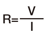
A simple way to measure the earth resistance is to drive an auxiliary earth electrode C, into a point distant from the grounded earth electrode under test E. An AC voltage V is applied between the two electrodes, dividing the AC voltage applied by the current that flows between the electrodes E and C. The earth resistance value R is given by the formula:
However, the earth resistance value obtained, R, includes the earth resistances of electrode E under test but also the resistance of the auxiliary electrode C.

When observing the potential distribution curve (in the above figure), a flat portion can be observed. This corresponds to the drop-of-potential due to the earth resistance of the earth electrode E.
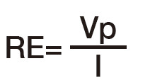
In order to measure only the earth resistance of the electrode under test E, another auxiliary electrode P is driven into the ground between electrode E and C and a voltmeter is used to measure the potential across P-E , that is Vp.
Then the earth resistance RE value is given by the formula:

Electrodes such as P and C driven into the ground for measurement are called as auxiliary earth electrode. (Electrode P is called Potential electrode and C Current electrode.)
The reason why an AC current is used for earth resistance measurements is because a DC current would cause a chemical reaction*, similar to water electrolysis, with moisture in the soil and gradually blocking the flow of DC current.
* Bubbles of hydrogen and oxygen arise around electrodes.
The test current frequency employed by earth testers are frequency bands other than the commercial ones (16Hz, 50Hz, 60Hz, 400 Hz) in order to reduce noise effects during testing.
Modern electronic earth testers are almost immune to noise effects by using special hardware and software filters, including the automatic selection of the test current frequency.