
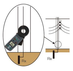
This can be made without using any auxiliary earth electrodes and without disconnection of the single earth electrode from the rest of the installation.
Let’s regard earth resistance under test as Rx, and the other earth resistances as R1, R2, Rn, see the below figure.
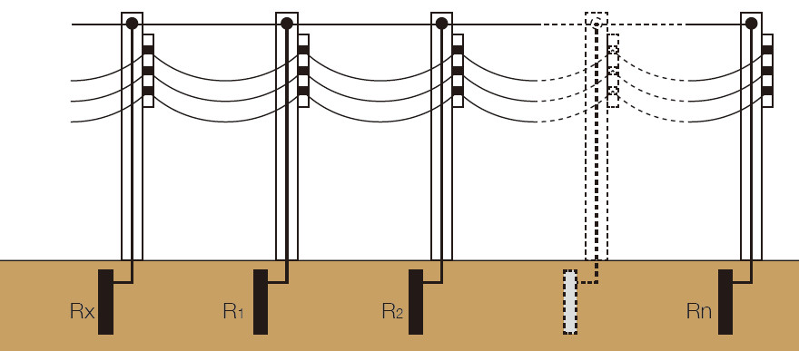
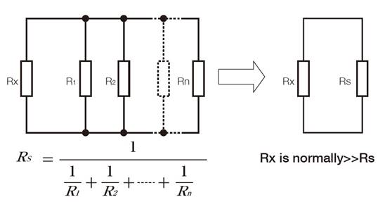
Normally in a distributed power line system as in the above figure, the earth electrodes R1, R2 Rn can be considered as resistors connected in parallel.
The total earth resistance (Rs) of this circuit will usually be very small compared to the resistance of a single earth electrode (Rx) because there are many electrodes in parallel.
Following is an equivalent circuit diagram of this circuit.
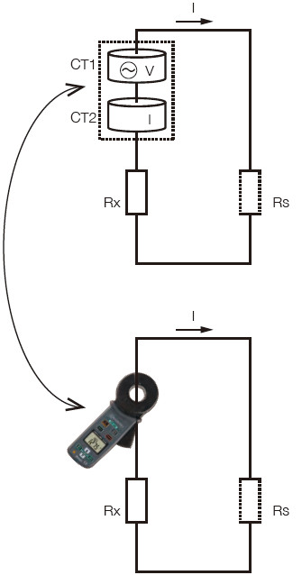
If we consider this equivalent circuit diagram, when the voltage injection transformer CT1 of the earth clamp meter induces a voltage V on the conductor joining the two resistances, a current I will flow through the conductor and the earth resistance Rx and Rs.
The amount of current I flowing is in inversely proportional to resistance R (combined resistance: Rx+Rs).
Such current can be measured by the detection current transformer CT2 and then the value of R can be obtained by Ohm’s low calculation.
The resultant R can be considered equal to the Rx under test since the Rs can be negligible enough against Rx.
Kyoritsu Earth Clamp Kew 4200/4202 are instruments that includes the voltage injection transformer CT1, the current detection transformer CT2 and all the necessary electronics for obtaining the measurement result in ohms.